
A Cell Contact System (CCS) is an integrated assembly used inside a lithium battery module. It combines electrical interconnection and signal-sensing functions into a single component.
In many battery module designs, the CCS is assembled onto the cell terminals and integrates components such as busbars, sensing circuits, temperature sensors, connectors, and insulating structures. This can reduce the number of individual components that need to be assembled separately and create a more standardized manufacturing process.
For battery manufacturers, this integration also creates opportunities for automated assembly, laser welding, electrical testing, and automated optical inspection.
This guide explains what a CCS is, what components it contains, how a CCS is manufactured on an automated production line, which factors affect joint quality, and what to consider when selecting a CCS production line.
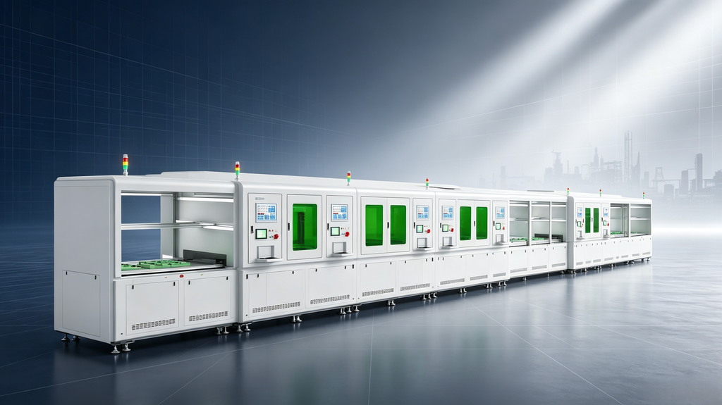
Why Does the CCS Architecture Matter?
A battery module needs to perform several functions at the same time.
The cells must be electrically connected, their voltage and temperature must be monitored, and the internal assembly must remain mechanically stable.
Traditionally, these functions could involve multiple separate components, including busbars, wire harnesses, sensors, brackets, and connectors.
A CCS integrates many of these functions into a more compact assembly. The resulting component can then be positioned, joined, tested, and inspected as part of a standardized manufacturing process.
For high-volume battery manufacturing, this integration can support greater production consistency and make automated assembly more practical.
What Does a Cell Contact System Consist Of?
A typical CCS may combine several major component groups.
What Does the Flexible Printed Circuit Do?
An FPC (Flexible Printed Circuit) carries voltage sampling and temperature-sensing signals to a connector.
Its flexible structure allows the circuit to follow the geometry of the battery module and can accommodate certain dimensional variations within the assembly.
What Do the Busbars Carry?
Busbars provide the main electrical connection between cells.
Depending on the battery design and electrical requirements, different conductive materials and surface treatments may be used. Aluminum, copper, and nickel-plated materials can all be found in battery interconnection applications.
The final material selection depends on current requirements, mechanical structure, welding process, weight, corrosion considerations, and the specific battery design.
What Is the Structural Carrier For?
An injection-molded plastic carrier can hold the FPC, busbars, and other components in the required geometry.
It may also provide insulation and maintain the required spacing between conductive components.
Where Are the Terminal Connection Points?
Terminal connection points are the locations where the electrical interconnection is joined to the battery cell terminals.
These areas require careful control of positioning, welding conditions, and inspection because the available joining area can be relatively small.
How Does the Connector Interface Work?
A connector provides the interface between the CCS sensing circuit and the battery management system (BMS).
This allows voltage and temperature signals collected from the battery module to be transmitted to the relevant control system.
Because the CCS combines electrical connection and sensing functions, joint reliability, positioning accuracy, electrical testing, and inspection capability are important considerations when specifying a CCS production line.
How Is a CCS Produced on an Automated Production Line?
An automated CCS production line can typically include several stages. The exact process sequence depends on the CCS structure, materials, production capacity, and customer’s manufacturing requirements.
1. Component Loading and Positioning
Busbars, FPCs, and plastic carriers are supplied from trays, reels, or other material-feeding systems and placed into dedicated fixtures.
Fixture design is important because it establishes the positioning reference for subsequent assembly, riveting, welding, and inspection processes.
2. Visual Alignment
Vision systems can verify whether components are present, correctly positioned, and correctly oriented before joining takes place.
Early detection of missing or incorrectly positioned components can prevent defective assemblies from continuing into downstream processes.
3. FPC and Busbar Assembly
The FPC and busbars are assembled onto the carrier.
Depending on the product design, this process may include film lamination or other bonding processes used to secure the FPC to the carrier before the busbars are positioned.
4. Multi-Point Hot Riveting
Pulse hot riveting provides mechanical fixation before the welding process.
Heated riveting tools soften and form plastic posts to secure the FPC, busbars, and carrier in their designed positions.
Because different riveting positions may have different material thicknesses or thermal characteristics, independent temperature control can be used to adjust process parameters according to the actual joint requirements.
5. Laser Welding
Laser welding creates the required electrical joints within the CCS assembly.
Weld quality depends not only on laser power, but also on part positioning, clamping, focus control, material condition, and welding path accuracy.
Depending on the product design and production requirements, different laser configurations can be considered to achieve the required cycle time and welding consistency.
6. Electrical Testing and In-Line AOI
After assembly and welding, the CCS can undergo electrical testing and automated optical inspection.
Electrical testing may verify continuity, insulation resistance, dielectric withstand, and other electrical characteristics required by the product.
AOI can inspect the physical condition and positioning of components and joints.
It is important to distinguish between full-inspection items and detection-rate-based inspection items, because different defect types may require different inspection criteria.
What Conditions May Affect CCS Joint Quality?
Several factors can affect the consistency of a CCS joint. These factors are normally evaluated together because a change in one process condition may influence another.
Surface Condition
Contamination, oxidation, oil, or other residues on the joining surfaces can affect welding consistency.
Cleaning and surface preparation should therefore be defined according to the material and welding process.
Positioning and Dimensional Variation
If a component is not correctly aligned with the cell terminal or welding area, the available joining window may be reduced.
Because some battery terminals provide a relatively limited joining area, positioning accuracy can have a direct influence on welding consistency.
Thermal Input
Laser energy and welding parameters need to be matched to the material and thickness being joined.
Higher energy input may increase penetration, but excessive energy can also increase the heat-affected area.
The appropriate process window should therefore be established through process validation for the specific material and joint structure.
Mechanical Stress
During riveting and clamping, mechanical pressure is applied to the CCS assembly.
Controlled compression can help maintain contact between components while reducing the risk of excessive mechanical pressure.
Process parameters and inspection criteria should be defined in the project technical proposal.
What Parameters Should You Confirm Before Ordering a CCS Production Line?
Equipment specifications are only useful when their meaning and test conditions are clearly defined.
Several parameters are particularly important when evaluating a CCS automated production line.
Positioning Accuracy at the Terminal
Automated CCS equipment may specify positioning accuracy in the range of a few hundredths of a millimeter.
For one reference configuration, positioning accuracy may be specified at approximately ±0.05 mm.
However, the final requirement depends on the CCS structure, terminal dimensions, fixture tolerance, and overall tolerance stack-up.
The actual positioning specification should therefore be confirmed against the customer’s product drawings and process requirements.
Takt Time and PPM
Production capacity should always be evaluated against the specific CCS structure.
For reference, some prismatic battery module and PACK production lines may operate in the 12–15 PPM range. However, the actual CCS assembly takt can vary according to the number of welding points, riveting points, testing requirements, product dimensions, and line configuration.
A CCS with a greater number of joining and inspection points may require a different cycle time.
Actual production capacity should be calculated for the customer’s specific product and confirmed in the technical proposal.
Changeover Time
Changeover time is the time required to switch the production line between different product variants.
If one CCS production line is expected to manufacture several module designs, changeover flexibility can have a significant effect on usable production capacity.
Changeover time depends on factors such as fixture design, product recipes, tooling, software parameters, and the number of components that require physical adjustment.
The supplier should provide a changeover procedure and corresponding reference time for the actual product variants planned for the line.
Inspection Coverage
Confirm whether AOI and electrical testing are integrated directly into the production line or performed at separate stations.
In-line inspection can identify defects before the product moves to subsequent processes, while off-line testing may be appropriate for certain products or production configurations.
The inspection scope, test points, detection criteria, and acceptance standards should be clearly defined before the equipment is finalized.
How Do You Decide Between Manual and Automatic CCS Assembly?
The appropriate automation level depends on production volume, product stability, labor requirements, quality standards, and future production plans.
Manual Assembly
Manual assembly may be suitable for prototypes, product development, service applications, or low-volume production.
The initial equipment investment is generally lower, but labor requirements and operator-to-operator variation can be higher.
Semi-Automatic Assembly
Semi-automatic equipment can be useful for pilot production and smaller batches where the product design is still evolving.
For example, material loading may be performed manually while welding, testing, or other critical processes are automated.
Fully Automatic Assembly
Fully automated CCS production lines can be suitable for higher-volume manufacturing where production consistency, traceability, cycle time, and labor efficiency are important.
The key consideration is not simply achieving the highest possible automation rate. The automation architecture should also match the stability of the product design and the customer’s production requirements.
For products that are still undergoing frequent design changes, excessive automation may increase engineering and changeover complexity.
Where Is a CCS Used?
Electric Vehicles
CCS technology is used in various EV battery module designs, particularly where integrated electrical interconnection and sensing are required.
The exact CCS structure varies according to cell format, module architecture, electrical requirements, and battery manufacturer specifications.
Energy Storage Systems
CCS assemblies can also be used in battery modules for energy storage applications.
ESS projects may involve different module sizes, sampling requirements, production volumes, and traceability requirements, so the CCS production process should be configured according to the specific application.
Industrial and Specialty Batteries
CCS technology can also be applied to industrial and specialty battery systems where integrated electrical connections and sensing can simplify internal module assembly.
The appropriate manufacturing approach depends on production volume, module structure, and product requirements.
What Has Changed Going into 2026?
As battery manufacturers develop new module designs, several factors are increasingly important when specifying a CCS production line.
Higher Sampling Density
Some battery module designs require more voltage and temperature sampling points.
A higher sampling density may require additional electrical test channels and greater flexibility in the CCS production system.
For this reason, future expansion capability is worth considering during the initial equipment specification.
Greater Traceability Requirements
Battery manufacturers may require production parameters, inspection results, and test data to be associated with a unique CCS or product ID.
Before ordering equipment, confirm which data needs to be collected, stored, and transferred to the customer’s MES or production management system.
Greater Changeover Flexibility
Manufacturers producing several module variants may require a production line capable of supporting multiple CCS configurations.
Fixture flexibility, programmable process parameters, recipe management, and controlled changeover procedures can all influence the ability of one line to support multiple products.
Specific production capacity, accuracy, testing capability, and automation requirements should always be calculated from the customer’s own product data and confirmed in the project technical proposal.
What Are the Key Takeaways?
- A CCS combines electrical interconnection and signal-sensing functions in an integrated battery module assembly.
- Busbars, FPC/FFC circuits, connectors, carriers, and other components can be integrated into the CCS depending on the product design.
- Automated CCS production may include component loading, visual alignment, assembly, pulse hot riveting, laser welding, electrical testing, and AOI inspection.
- CCS joint quality depends on surface condition, positioning, thermal input, clamping, welding parameters, and inspection capability.
- When evaluating equipment, confirm the positioning tolerance, product-specific takt time, inspection coverage, traceability requirements, and changeover procedure.
- CCS design and battery module design are closely connected, so the interconnect structure should be considered early in the module design process.
Pulse hot riveting provides mechanical fixation, while laser welding creates the required electrical joints.
Frequently Asked Questions
Is a CCS the Same as a Busbar?
No.
A busbar is primarily a current-carrying conductor. A CCS is an integrated assembly that may include busbars together with the signal-sensing circuit, insulating carrier, connectors, and other components.
Why Is Laser Welding Commonly Used for CCS Terminal Connections?
Laser welding is a non-contact joining process that can provide a relatively concentrated heat input and a narrow heat-affected area.
This can be useful when joining conductive components around battery cell terminals, where process control and positioning accuracy are important.
Other joining methods may also be used depending on the battery design, materials, and manufacturing requirements.
Can One CCS Production Line Handle Several Module Designs?
Potentially, yes, provided the line is designed with the required flexibility.
Adjustable fixtures, programmable welding parameters, recipe management, and suitable changeover tooling can allow one production system to support multiple product variants.
However, the achievable flexibility depends on the differences between the products. The required tooling, process changes, cycle time, and investment should be evaluated before the equipment is specified.
What Inspection Is Typically Specified on a CCS Line?
A CCS production line may include:
- Pre-process vision inspection for component presence and orientation
- Post-weld AOI for joint and component inspection
- Electrical testing for continuity
- Insulation resistance testing
- Dielectric withstand testing
The exact inspection scope should be determined according to the customer’s quality requirements and CCS structure.
How Does CCS Affect Battery Module Design?
The CCS can influence both the electrical layout and mechanical structure of the battery module.
Because the CCS spans multiple cells and connects multiple sampling points, cell arrangement, terminal orientation, busbar position, and sensing-point location generally need to be considered during module design.
Is On-Site Installation and Commissioning Included?
Jialuo Intelligent provides on-site installation and commissioning through engineers and technicians.
For overseas projects, interpretation support is also available to facilitate communication between the Jialuo engineering team and the customer’s local team.
Equipment is pre-commissioned at our Shenzhen facility before shipment.
For reference, domestic steel strap line projects can typically be completed within approximately 7–10 days, while other domestic module line projects may require around 30 days. For overseas projects, on-site installation and commissioning can typically be completed within approximately one month, depending on project scope, equipment configuration, and site conditions.
How Should Reference Parameters Be Used?
Technical parameters presented in product materials should be understood as reference values for a specific equipment configuration.
Actual takt, accuracy, production capacity, testing capability, and automation level should be calculated based on the customer’s:
- CCS structure
- Cell and module specifications
- Process route
- Production capacity
- Quality requirements
- Traceability requirements
The final technical specifications should be confirmed in the project technical proposal and equipment acceptance criteria.
About Jialuo Intelligent
Shenzhen Jialuo Intelligent Technology Co., Ltd. develops intelligent equipment and production-line solutions for lithium battery manufacturing.
Our product portfolio includes:
- Battery Module PACK Production Lines
- Battery Module Steel Strap Forming Lines
- CCS Automated Production Lines
- Prismatic Cell Cover Plate Assembly and Welding Equipment
- Battery Module Testing Solutions
- Customized Lithium Battery Automation Equipment
Founded in 2008, Jialuo Intelligent has focused on intelligent equipment for the new energy and lithium battery industry since 2019.
Our engineering capabilities cover mechanical design, automation control, equipment integration, line commissioning, and customized manufacturing solutions.
Planning a CCS Production Line?
Every CCS project starts with a different product design.
Busbar dimensions, riveting point count, sampling density, FPC structure, welding requirements, inspection scope, and traceability requirements can all affect the final production-line configuration.
If you are planning a new CCS production line or upgrading an existing CCS manufacturing process, share your product drawings and process requirements with our engineering team.
We can evaluate the required process route and develop a CCS automated production solution based on your product structure, production capacity, and quality requirements.
Shenzhen Jialuo Intelligent Technology Co., Ltd.
Room 101, Building 2, No. 8, Chengguang Industrial Park, Kukeng, Dafu Community, Guanlan Street, Longhua District, Shenzhen, China
Email: jch@cnjialuo.com
WhatsApp: +86 181 2473 5015
Jialuo Intelligent | Battery Automation Solutions